Before installation, release the brakes and ensure that the brake chamber pushrod is in its initial position. If a dual-chamber spring brake actuator is present, the air pressure within the spring brake system must be maintained above 6 bar (pressure exceeding 6 bar compresses the spring within the parking brake chamber), thereby keeping the brake chamber pushrod in its initial position.
Clean the splines on the camshaft and apply a coating of grease or anti-wear lubricant.
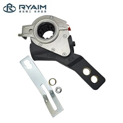
Place 2 to 3 washers onto the splined shaft (the exact quantity may be determined based on actual requirements to ensure that the lever of the automatic slack adjuster is centered within the yoke of the brake chamber pushrod during installation).
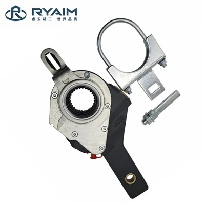
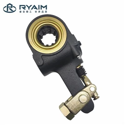
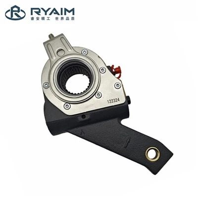
Install the slack adjuster onto the S-camshaft; the arrow marked on the adjuster housing must align with the direction of braking (i.e., the direction in which the brake chamber pushrod extends). Using a wrench, turn the hexagonal nut at the end of the adjuster clockwise (Note: The use of power wrenches or impact tools is strictly prohibited) to thread the adjuster into the yoke (U-fork) of the brake chamber pushrod until the hole on the adjuster naturally aligns with the corresponding hole in the yoke. Lubricate the cylindrical pin, insert it smoothly through the aligned holes in the yoke and adjuster, and secure it with a cotter pin. (Note: The hole on the slack adjuster *must* be perfectly aligned with the hole in the pushrod yoke.)
Mount the slack adjuster's mounting bracket or anchor plate onto the fixed bracket located on the axle camshaft bearing housing, and secure the plate to the bracket using bolts. Do not fully tighten the nuts at this stage. Rotate the control arm away from the adjustment nut until it reaches its designated initial position (at this point, significant resistance will be encountered-making it impossible to rotate the control arm by hand-which ensures the correct clearance is established between the brake lining and the brake drum); then, fully tighten the bolts securing the control arm bracket. For vehicle models equipped with a visual indicator, the indicator must be seated firmly into its mounting slot before tightening the bolts on the control arm bracket.
Secure the slack adjuster to the camshaft using washers and a circlip. At this stage, ensure that the axial clearance of the adjusting arm is a = 0.50–2.00 mm.
Using a 12 mm wrench, turn the hexagonal adjusting nut on the adjusting arm clockwise (applying low torque until no clicking sound is heard) until the friction lining makes contact with the brake drum; then, turn the hexagonal nut counter-clockwise by 3/4 of a turn (applying higher torque, at which point a clicking sound will be heard). Note: Do not use an electric impact wrench or pneumatic tool.
Once installation is complete, cycle the air pressure system (inflate and deflate) 30 to 60 times to finalize the adjustment of the self-adjusting arm. During the inflation and deflation cycles-specifically at the moment braking concludes-the self-adjusting function can be verified by observing the hexagonal head of the worm gear automatically rotating clockwise, or by gently resting a hex wrench on the adjusting nut and observing it turn clockwise. After the assembly has been installed, it is recommended to apply the vehicle's brakes continuously approximately 30 to 60 times. This process allows the brake linings and brake drums to bed in, ensuring that the self-adjusting arm operates correctly.